Introduction
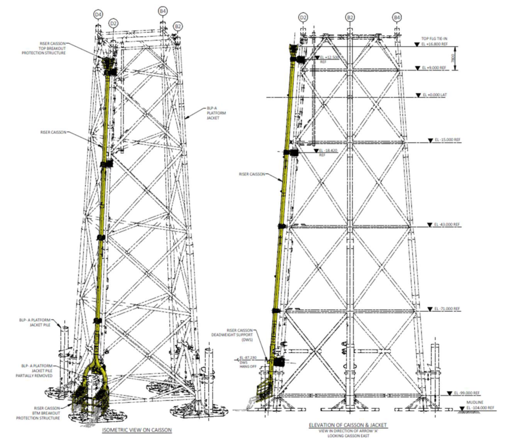
Dee Subsea carried out the detailed design of a dead weight support clamp, jacket clamps/guides and bolted guides to support a new retrofit caisson riser on a major North Sea pilot Enhanced Oil Recover (EOR) project in 2022.
We assessed friction grip bolting for the clamps against the requirements of ISO 19902 for ‘slip’ and ‘contact’ conditions. We carried out local design checks for the clamps and guides in accordance with Eurocode 3.
Due to the presence of an existing jacket pile, the 51″ diameter caisson riser split from the main straight section into two legs using a Y-splice arrangement straddling either side of the pile guide. A horizontal trunnion support member was located just below the caisson split at dead weight support elevation.
Dead Weight Support
The dead weight support is a ‘steel to steel’ friction grip clamp, incorporating a half-shell ‘saddle’ to receive the caisson horizontal trunnion support member at the Y-splice arrangement.
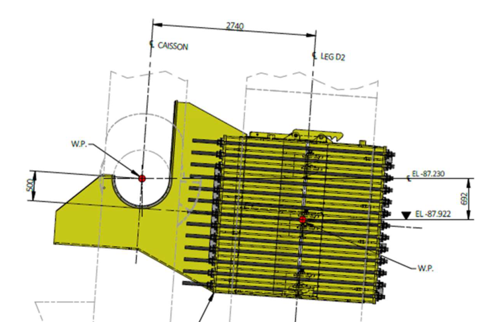
The dead weight support clamp has a nominal clamp ID of 2200mm, with clamp length and width of 2650mm and 2700mm respectively, and adopts 26 No. M52 bolts. The total in-air weight of the dead weight support clamp was approximately 21te including tensioning bolts. We designed a ballast counterweight to allow the dead weight support clamp to be installed with the door braced open.
Jacket Clamps/Guides
The jacket clamp/guide assemblies consist of a jacket friction grip clamp and a riser caisson guide, adopted at two locations on the jacket. The guide components were designed to transfer loading from the caisson in bearing back to the friction grip clamp on the jacket leg.
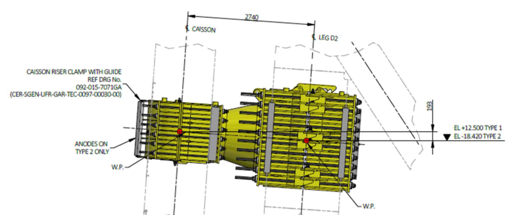
The friction grip jacket clamps have a nominal clamp ID of 1600mm and a clamp length and width of 2100mm and 2050mm respectively. The jacket clamps adopt 20 No. M52 bolts.
The caisson riser guides have an ID of 1362mm complete with 25mm polychloroprene bonded to the shell with 2mm thick PTFE bonded to the polychloroprene for an overall net ID of 1308mm suitable for the 1295mm OD caisson riser. Each guide adopts 12 No. M36 pretensioned bolts to prevent slip and separation of the guide halves.
The total in-air weight of each jacket clamp/guide was approximately 17te including tensioning bolts (in-air clamp) and 18t including tensioning bolts and anodes (subsea clamp).
Bolted Guides
At two elevations on the jacket, there were suitable existing supports from the jacket leg via stubs, with bolted interface plates to facilitate attachment of caisson riser guides. Therefore bolted guides were connected to the existing jacket at these two locations.
The guide half attaching to the existing plate includes structural ‘hook’ details to aid alignment during installation and subsequent bolting. This includes adjustment bolts to assist with final positioning. Oversized bolt holes were incorporated into the new plates to assist lining up with existing bolt holes.
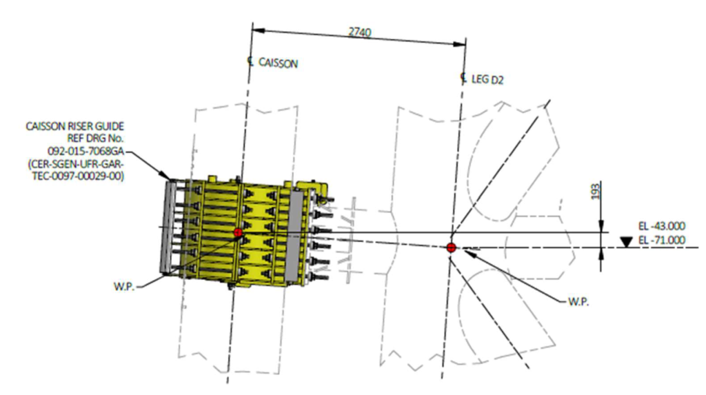
The guide component is similar in arrangement to the jacket clamp/guide, except that two sets of bolts are incorporated. One set of 12 No. M36 bolts on the guide half that attaches to the existing bolted plate, and 12 No. M36 bolts on the outer half of the guide.
The total in-air weight of each bolted guide was approximately 5te including bolts.
Additional Work
In addition, we carried out the design of installation aids including guide arms, latch plates, alignment shims, lift points, tie bars and sidepull/holding padeyes. All installation aids were designed in accordance with Eurocode 3.
We also carried out an extensive tolerance study, considering existing jacket tolerances and clamp/guide fabrication tolerances. Additional analysis of the caisson was carried out considering the range of possible tolerances. From this analysis, potential pull-in loads and residual guide loads were established which were considered in the design of the clamps and guides.
Additional finite element analysis of the clamps was carried out, which also considered the range of existing jacket leg tolerances (from survey data and EEMUA limits) along with clamp fabrication tolerances.
For more information about this project, our services and how we can help you, please contact us.